AECOsim Building Designer V8i should not be installed on the same workstation as an existing AECOsim Building Designer V8i v08.11.xx Technology Preview (“beta”) release. Installing AECOsim Building Designer V8i over an existing AECOsim Building Designer V8i v8.11.xx installation can cause incompatibilities and data loss. You must uninstall the beta release, and then install the commercial release.
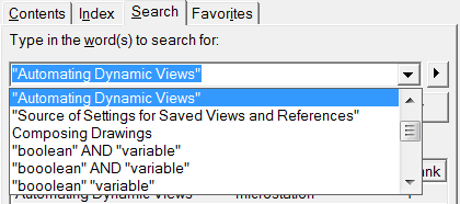
To Create a Deployment Image
In an Explorer window, double-click the AECOsim Building Designer V8i setup executable.
![]()
The AECOsim Building Designer V8i Installer dialog opens.
Select the “Extract installation package only” option and turn on the “Create Deployment image” check box.
By default, the installation package will be extracted to C:\BentleyDownloads\AECOsimBuidlingDesigner_v08.11.09.xxx, as shown in the “Extract to this folder” field.
To change the location to which the installation package is extracted:
In the “Extract to this folder” field, enter the drive and path to a different folder.
or
Click the Folder icon to the right of the field and browse for a different folder.
Click OK on the AECOsim Building Designer V8i Installer dialog.
When the package gets extracted to the AECOsimBuildingDesigner_08.11.09.225 folder, you have a choice to select “Create Deployment” which will create an image installation or “Setup.exe” to install the product
In the AECOsim Building Designer V8i setup wizard, all the components required by the application appear with a status of "Required".
![]()
This setup wizard remains open in the background.
(Optional) Click the Advanced Settings button.
The Advanced Settings dialog opens. This is where you can make the required settings in the Advanced Settings dialog and click OK. Proxy settings for internet connections may be different at each location and it is necessary to have an internet connection during the installation of AECOsim Building Designer and/or (MicroStation V8i SS3) since the installer searches the internet for necessary pre-requisite components.
Ok the Advanced Settings and Click Create.
In the AECOsim Building Designer V8i Setup dialog, click Next and the installation will begin.
![]()
![]()
The End-User License Agreement page opens.
After reading the license agreement, click the "I accept the terms in the License Agreement" check box if you understand and agree to the License Agreement Terms and Conditions. Click Cancel if you
decline the License Agreement Terms and Conditions.
*Note that agreeing to the license agreement is required in order to install the product.
Click Next.
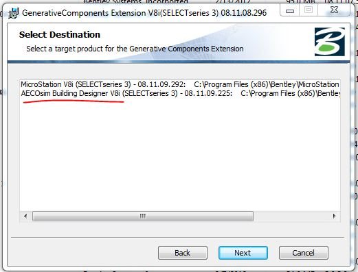
The Destination Folder page opens. This page shows the folders where the product will be installed.
(Optional) To change the directory where the deployment image will install the product, click the Change button below the “Install AECOsim Building Designer V8i To” field.
In the “Change Destination Folder” page that opens, browse to the drive and folder you want to install the product in,then click OK.
(Optional) To change the directory where the deployment image will install the workspaces, click the Change button below the “Install Workspaces To” field.
![]()
![]()
Click Next.
The Configure Shortcuts page opens.
(Optional) Select one or more of the following check boxes to indicate the location(s) where you would like a shortcut to AECOsim Building Designer V8i created when you install from the deployment image:
Start Menu (selected by default)
Quick Launch toolbar
Desktop
![]()
Click Next.
The Choose Setup Type page opens. Here you can select whether you want the deployment image to install a Typical or Custom setup.
Typical — installs the product with the most common features and NO customizations.
Custom — lets you select which features you want to install.
To do a typical installation, click Typical. When the Ready to install page opens, click Install.
or
To customize your installation, click Custom.
The “Product Features” page opens. Here you can select which features you want to install from the deployment image. There are six categories of features: Required Files, Workspaces, Application Documentation,
Utilities, File Association, Building Sample Projects and ProjectWise Desktop Integration.
![]()
The File Association category allows you to associate file types with AECOsim Building Designer V8i. For example, if you select the AECOsim Building Designer V8i design files subcategory, the installation will
associate the application with dgn, dgnlib, rdl, cel, hln, and sht file extensions. Click the plus sign (+) next to a category to see the features in it.
The amount of disk space required to install a feature appears when you select the feature. Click the down arrow next to a category or feature to select how you want it installed. You also can choose not to install a category or feature.
Click Install.
Click Finish to exit the AECOsim Building Designer V8i Setup Wizard.
![]()
![]()


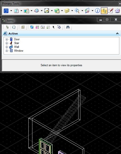
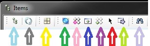

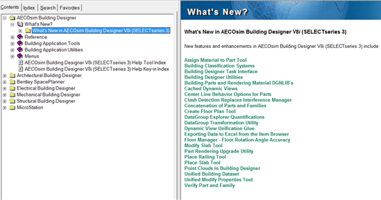
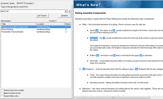
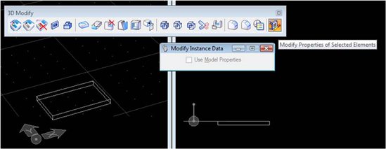
 Refresh Active Tree > This will reset the “active” Items so that only the active or selected Item is displayed.
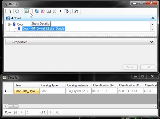
 Details > This displays information for a specific item that’s selected in the Items Dialog Box.
 Transparent > Changes the View Display style to Transparent.
 Highlight > This identifies the element selected in the Items dialog and will highlight that element in the 3D model
 Zoom> This zooms-in on the element selected in the Items Dialog Box in the 3D Model.
 Select > Selects the element(s) in the 3D model that are highlighted in the Items dialog box.
 Items Display Settings > Controls the view zoom options when selecting items in the Items dialog box.
 Search > Search for items that are not easy to find in the Items dialog box, this tool can be useful when working with an extensive list of elements in the 3D model.